Series and Parallel Circuits

jumblecircuit

All hams should have at least a limited understanding of basic circuits, and this means being able to differentiate between series and parallel components.

Besides numerous license exam questions (dozens below in green boxes; knowing helps you pass the exams), some technical discussions in ham radio will throw the terms around so let’s explore the matter here.  In addition to our own presentation, some excellent web references are given at the end for further (and often more interesting) information.

T6D11-2018

Before jumping into circuits, let’s discuss series and parallel connections.  Visualizing this will help us understand series and parallel circuits.


As the name suggests, series connections are lined up end-to-end.

series res

We’re demonstrating with resistors but the principle applies to any two-terminal component: capacitors,  inductors, diodes, cells/batteries, and light bulbs can all be wired in series with two or more of each (or a mix of different parts).  Lining them up terminal to terminal makes a series connection.

T6C12-2018

Schematically, 3 parts in series looks like this:

Series schem

From this simple schematic we intuitively see that the current flowing through a series string has to be the same though the chain; there is nowhere else for electrons to flow (current).

T5D13-2018

Equal current is one way of defining a series circuit.

T5A13-2018


Also as the term suggests, parallel connections are side-by-side.

parallel res

Again, demonstrating with resistors and again, the principle applies to any two terminal component.  Arranging components across each other makes a parallel connection.

T6C13-2018

Schematically, 3 parts in parallel looks like this:

Parallel schem

From this simple schematic we intuitively see that the voltage across parallel components must be the same.

T5D16-2018

Equal voltage is one way of defining a parallel circuit.

T5A14-2018


We just learned that current is the same through components in series, and voltage is the same across components in parallel.  What about  the voltage across series components, and current through parallel components? Continue reading
Coaxial Cable (Coax)

Because it’s commonly used in radio work, every ham should be familiar with coaxial cable, often simply called coax.

Coaxial cable is most often used between the transceiver (or T/R switch) and antenna.  In this application coax acts as the feed line (AKA transmission line) to carry transmitted and received RF signals between the antenna and radio.  Other types of feed line can be employed but coax is used by many hams because it is easy to work with and readily available.

T9B03

Coax  is a type of electrical cable that has an inner conductor surrounded by a tubular insulating layer, surrounded by a tubular conducting shield. Most coaxial cables also have an insulating outer sheath or jacket.  The term coaxial comes from the inner conductor and the outer shield sharing a geometric axis.

300px-Coaxial_cable_cutaway.svg

To be useful coaxial cable must be terminated with mating RF connectors.  An experienced ham may terminate their own coax; at greater cost they may purchase ready-made and tested assemblies.

coax ca assy  coax ca assy2

A wide variety of coaxial cable and assemblies are available with different characteristics. A quick summary of the important features:

  • Characteristic impedance
  • Signal loss
  • Power capacity
  • Diameter/weight
  • Flexibility
  • Environmental resistance

A seventh important characteristic of coax is velocity factor but that is a more advanced topic of lesser importance so we’ll simply mention it here.

Coaxial cable selection for each installation may be a compromise between features, requirements, and cost. The ham has to factor in what he needs or wants, what is available, and what it costs.


A quick look at these features of coaxial cable: Continue reading

SWR

The standing wave ratio (SWR) is an important topic to hams regardless if they are working HF, VHF, UHF or any other frequency range allocated to radio amateurs.  Unfortunately it is technically involved and somewhat complex so is not intuitive or easy for non-technical folks to understand.  We’ll give a simplified explanation of SWR here and give you a basic idea of its significance and how hams relate to it.

The simplest way to think of SWR is as a measure of impedance matching.  Most commonly it is looking at the impedance differences between transceiver, transmission line (more often coaxial cable), and antenna.

T7C03-2018

Assuming that all modern radios and cable have 50Ω impedance, the real SWR of interest boils down to the match between the transmission line and antenna.

As we mentioned in a previous post, when impedance of a source equals load impedance the best possible signal coupling occurs. Conversely, when impedances are not the same, signals couple poorly.  This is true of all electronics circuitry involving AC waveforms.

In amateur radio SWR focus is on transceiver to antenna coupling where we want to maximize RF power transfer in both transmit and receive modes.  When impedances do not match, received signals will be weak or non-existent; when transmitting, power will not radiate well from the antenna.  The ideal or “perfect” SWR for best possible transmit/receive coupling is 1:1, meaning a 50Ω radio/transmission line to a 50Ω antenna.

T7C04-2018

SWR is simply the ratio of two impedances being measured.  It is commonly expressed in the X:X format and the larger value is always given first, regardless of which side is higher.

T7C06-2018

With a 50Ω radio and 50Ω coax cable, a 4:1 SWR could indicate either a 12.5Ω or a 200Ω load (antenna).  Similar examples for 50Ω cable are contained in the General class exam pool:

G9A09-2015G9A10-2015A ham’s main concern with high SWR is significant power reflected back from the load, which stresses the transmitter power amplifier.  While a 1:1 SWR is ideal, practically speaking, 1.5:1 or less is good.  Many modern transceivers automatically reduce transmit power with a SWR greater than 2:1.

T7C05-2018

SWR can be measured Continue reading

Dummy Load

Radio amateurs should be familiar with the term dummy load, which is a RF-friendly substitute for an antenna when testing a transmitter or piece of equipment such as a Watt meter.

Dummy1   Dummy2   Dummy3

A dummy load is somewhat generic, also having industrial and commercial uses.  As applied in ham radio, it electrically simulates an antenna to allow a transmitter to be tested without radiating radio waves, typically at 50Ω to match transmitter output impedance.

T7C01-2018

Dummy loads are rather simple—  just a big resistor and some way to dissipate heat, all in a package that must be non-reactive, meaning it provides insignificant capacitance and inductance.

T7C12-2018

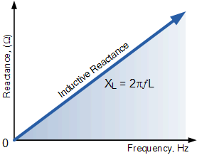
Why must a dummy load be non-inductive?  Because of impedance (practically speaking, AC resistance), which increases with frequency based on the formula of inductive reactance XL=2πfL.

XL

Most common power resistors are wire-wound, which have significant inductance.  So RF dummy loads must use resistors with little or no inductance.

As an example, this four-resistor series combination using common Dale metal-clad resistors measures 49.4Ω at 0Hz (DC).  Sounds like a perfect dummy load, right?

DSCN4385

Unfortunately  it also has Continue reading

Flat Ground Strap

Ever wonder why RF grounds should be flat straps and not regular wires?

This is because ordinary wires are not good conductors at frequencies higher than 50-60Hz. This complicates wiring and bonding requirements.

Impedance (effectively, AC resistance) of a conductor increases with frequency and length due to inductive reactance.  The higher the frequency, the greater the impedance.

XL

All conductors have some measurable inductance, and it doesn’t take much to yield significant impedance.  At KHz or MHz frequencies, long round wires might present hundreds or even thousands of Ohms impedance; not suitable for grounding.

A good ground has less than one ohm impedance.  This is a genuine safety issue.

G4C05-2015

Since inductive reactance increases with frequency and length, safety grounds and module bonds need to be something other than long round wires when radio frequencies are involved.

When high frequency grounding is required, use short, wide, and flat conductive straps.  The high aspect ratio minimizes electrical inductance vs. a round wire, as does a short conductor.  This lowers the ground wire’s impedance at higher frequencies.

T4A08-2018

So now you know.  Keep it flat and short (KIFS is a lousy acronym).

It’s not just a suggestion; this one might just bite you if you don’t heed the guideline!

Impedance

Impedance is an important subject in amateur radio so we want to spend a little time discussing it here.  Several topics on this site will involve impedance so it’s good to have this basic concept well understood.

In ham radio work we deal with impedance in transmission lines, antennas, transmitter outputs, receiver inputs, microphones, speakers, headphones, and other devices.  Impedance matters everywhere a signal couples to something different.

Basic resistance (R) is what opposes current in a DC circuit, and all components have measurable resistance.

T6A01-2018

But things get more complicated in AC circuits.  Capacitors and inductors (coils) oppose change.  This includes alternating current, a characteristic of audio, video and radio frequencies.   The properties of capacitance and inductance have well-defined opposition to AC which varies by signal frequency.

G5A02-2015

All components have measurable capacitance and inductance so there is always some reactance (X) in a circuit.  There are two flavors of reactance: capacitive and inductive.  Interestingly, they respond oppositely to signal frequency.  Inductive reactance (XL) goes up with frequency while capacitive reactance (XC) goes down.

When you add the constant resistance in a circuit to the capacitive and inductive reactance, the result is impedance (Z=R+jX).  In broad terms, it can be considered “AC resistance”, which is legitimate when we don’t care about the complex phase angle part of the equation.  Resistance plus reactance equals impedance (Z).

T5C12-2018

Like DC resistance, impedance (AC resistance) is measured in ohms.

T5C13-2018

OK so far?  Click on the many hyperlinks in this article for more detail, along with helpful links below.  Don’t worry, you only need to grasp the basics here; high-level math is not necessary for a working knowledge of impedance.

Now that you know what impedance is, the next important thing to understand is that when an AC signal interfaces with a new circuit, the impedances should match.

When impedance of a source (ZS) equals the load impedance (ZL), the best possible signal coupling occurs. Conversely, when impedances are not the same, signals couple poorly.

G5A07-2015

The maximum power-transfer theorem says that to transfer the maximum amount of power from a source to a load, the load impedance should match the source impedance (ZS=ZL).

G5A08-2015

Good examples of impedance matching are: audio amplifier output to speaker (8Ω); transceiver RF circuits to antenna feed line (50Ω); microphone to audio input (2000Ω).

Impedance matching can be accomplished by Continue reading

Understanding Antennas-A Simplified Perspective

A PowerPoint slideshow, Understanding Antennas / A Simplified Perspective for Ham Radio Operators is downloadable here: Understanding Antennas-A Simplified Perspective

This presentation provides a working understanding of amateur radio antennas without being overly technical or dry.

The target audience is newer hams with limited knowledge of antennas.  It is presented at the Technician license level. You will see Continue reading