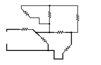
All hams should have at least a limited understanding of basic circuits, and this means being able to differentiate between series and parallel components.
Besides numerous license exam questions (dozens below in green boxes; knowing helps you pass the exams), some technical discussions in ham radio will throw the terms around so let’s explore the matter here. In addition to our own presentation, some excellent web references are given at the end for further (and often more interesting) information.

Before jumping into circuits, let’s discuss series and parallel connections. Visualizing this will help us understand series and parallel circuits.
As the name suggests, series connections are lined up end-to-end.

We’re demonstrating with resistors but the principle applies to any two-terminal component: capacitors, inductors, diodes, cells/batteries, and light bulbs can all be wired in series with two or more of each (or a mix of different parts). Lining them up terminal to terminal makes a series connection.

Schematically, 3 parts in series looks like this:
![]()
From this simple schematic we intuitively see that the current flowing through a series string has to be the same though the chain; there is nowhere else for electrons to flow (current).

Equal current is one way of defining a series circuit.

Also as the term suggests, parallel connections are side-by-side.

Again, demonstrating with resistors and again, the principle applies to any two terminal component. Arranging components across each other makes a parallel connection.

Schematically, 3 parts in parallel looks like this:

From this simple schematic we intuitively see that the voltage across parallel components must be the same.

Equal voltage is one way of defining a parallel circuit.

We just learned that current is the same through components in series, and voltage is the same across components in parallel. What about the voltage across series components, and current through parallel components? Continue reading


