APRS

You may have read or heard the term APRS.  This four letter acronym isn’t self-explanatory but is popular and important enough that we should cover the basics.

Do you need APRS? Unlikely.  Do you want it? Maybe.   Planning to buy a new VHF/UHF radio and wonder if this is a feature worth paying for?  Read on.  APRS is a big topic with way more detail than we can present here so we’ll give you a general idea of what it involves along with some research links to answer these questions yourself.

For starters, APRS stands for Automatic Packet Reporting System.

T8D02-2018
Some publications mistakenly call it Automatic Position Reporting System

Refer to our packet topic for a background on what packet radio is all about.  What makes APRS a specialized form of packet is what info is transmitted.

APRS supports four data types, including Position/objects, Status, Messages and Queries.  The position packets contain latitude and longitude, a symbol to be displayed on a map, plus optional fields for altitude, course, speed, radiated power, antenna height above average terrain, antenna gain, and voice operating frequency.

While APRS can send packets over greater distances on HF bands, it is more commonly used with VHF FM (2m) radios to share data of interest in the local area such as GPS coordinates, weather, alerts, announcements, and such.

APRS info and messages can be directly between hams but more commonly, packet data is collected by local repeaters (gateways) and sent to the APRS Internet System (APRS-IS) for retrieval anywhere by anybody with a web browser.  Meaning your unlicensed spouse can see where you are located (technically, your transceiver) at any given time.  It is not a one-way system; APRS both transmits and receives packet data.

Also unlike normal packet radio, APRS blindly sends out data addressed to no one in particular (unconnected). Two things to know about this system: 1) no error correction (clean, strong signals required), 2) someone or something must be monitoring to be useful (another APRS ham or internet gateway).

In addition to several good references below, an excellent resource worth reading right now: Intro to APRS (PDF file link), a presentation prepared by John Gorkos AB0OO of the Joplin (MO) ARC.   It discusses what the system is not, significant info you can get through it, what you can do with it (note two separate sections for this), and suggests next steps for getting involved with APRS.

Given all the possibilities above, the primary use of APRS in ham radio is to have a transmitter location reported to a central database periodically so that others can see where a mobile/portable ham is located.

T8D05-2018

This makes APRS particularly useful for public service events and emergency communication (EmComm) situations where managers can easily track mobile resources who have messaging capabilities.

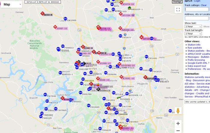
There are numerous web services for viewing APRS maps and data but the main one (and simplest) is  aprs.fi .  Click there and you will be taken to a local map showing locations of ham APRS transmitters in your own area.  Looks like this example:

APRS Map

In North America all APRS data is transmitted on 144.390 MHz.

APRSVHFworldmapXx

Just tune your VHF radio to your global frequency to hear the packet squeal, if you are wondering what it sounds like.

APRS requires not only a 2m FM transceiver but also a computer with display and TNC radio-computer interface, plus (normally) a GPS receiver.  Radios with APRS features built in cost more than ordinary mobile or handheld transceivers, mainly because Continue reading

Selective Calling & Tone Squelch

In a previous post we introduced the term squelch and how it was used in basic operation.  As mentioned there modern ham radio work (especially with repeaters) often involves other technologies that fall under a different category named selective calling, tone squelch being the most common form.

Selective calling is different from ordinary carrier or noise squelch.  In practice it is more of a security or channel sharing function.  Selective calling encompasses several similar technologies which largely do the same thing: prevent a transmitted signal from being received by other radios unless a particular code is entered by the sender.

From the Wikipedia article, “Selective calling is akin to the use of a lock on a door. A radio with carrier squelch is unlocked and will let any signal in. Selective calling locks out all signals except ones with the correct “key”, in this case a specific code.”

The most common form of selective calling in use by hams is a tone squelch system with the awkward name of continuous tone-coded squelch system (CTCSS).  Squelch in general is used to keep commercial and amateur radio repeaters from continually transmitting. Since a carrier squelch receiver cannot tell a valid carrier from a spurious signal (noise, etc.), CTCSS is often used as well, as it avoids false key-ups. Use of CTCSS is especially helpful where nearby repeaters may share the same frequency or in a high electrical noise or RF environment.

T2B02-2018

As the name implies, CTCSS sends out a continuous tone along with the transmit audio.  The tone is termed, “sub-audible”, although it is often a low audible frequency.  Most radio systems filter out these low frequencies so it is unlikely that you will hear the tone when listening to another ham unless you have an unusual radio and/or are wearing high fidelity headphones.

The CTCSS tone is selected by a repeater operator to avoid duplication with nearby repeaters on the same frequency.  In most cases, the objective is to reduce interference and not restrict legitimate access.  There are 100 established CTCSS frequencies but some are more commonly used than others.

CTCSS is often referred to as PL because it’s easier to say.  They mean the same thing but PL® (stands for Private Line) is a registered trademark of Motorola’s implementation and was the original employment of CTCSS.


Besides CTCSS, other forms of selective calling in use by hams include:

  • Selcall (mostly European)
  • Digital-Coded Squelch (DCS)
  • XTCSS

Why it matters to us

T2B04-2018Because various forms of selective calling prevent a signal from being re-transmitted (repeater) or received (simplex) without the proper code or tone, use of CTCSS or DCS is a possible reason other stations cannot receive you.  Especially on a repeater, if others cannot hear you it’s quite likely that you have the wrong code or your tone squelch is turned off.  How to know what the proper setting is?  Consult the repeater directory.


Some Useful Links

CTCSS – RadioReference

How radio “privacy tones” or CTCSS tones work – YouTube video

CTCSS – MDARC

Get the Right Signal Tone – Ham Radio School

Hey, Why Can’t I Access the Repeater? – Ham Radio School

Differences between CTCSS and DCS – Retevis

CTCSS & Tone Burst Ham Radio Repeater Access – electronicsnotes

A Historical and Technical Overview of Tone Squelch Systems – WA6ILQ

Repeater Related Terminology – Repeater Builder group

Squelch

Squelch is a funny word that is familiar to many of us without understanding what it really means.  Hard to improve on the definition beyond that in the Technician license exam question:

T4B03-2018

Most useful when using voice modes (phone), squelch makes radio operation more bearable by turning off the audio when there is no valid signal.  Without squelch our radios would be cranking out a lot of unwanted background noise.

The reality of both AM and FM radio (which we covered recently) is that there is electrical noise in the bands from many sources, natural and man-made.  This noise is often randomized so that it appears as hiss or fuzz (white noise) from radio receivers.  A squelch circuit mutes receiver audio to block the noise when there is no real signal.  Squelch acts as a noise gate which closes for random noise and opens when a real signal (such as modulated voice) appears on frequency.  How the squelch circuit determines what is a valid signal and what is noise varies; there are a few common techniques (refer to algorithm link in references below).

Squelch is built into more expensive broadcast receivers.  It may also be found on AM transceivers (particularly CB radios) and is a feature of nearly every FM amateur rig.

While less prone to electrical noise, FM technology is susceptible to a lack of true signal.  Traditional FM receivers use an LC tuning circuit that generates ‘hiss’ with no signal present.  You may have noticed this while tuning between stations  on your broadcast FM radio.  Since hams commonly use VHF/UHF FM transceivers for local chat and EmComm work, the squelch feature of our rigs is of particular interest.

Squelch setting is important because if you make it too tight you may not hear a weak signal; too loose and you get constant noise.  General good practice (at least a starting point) is to turn down the squelch until you hear background noise (hiss), then increase the threshold until the noise goes away, then just a little more.

Squelch threshold is always settable on your FM transceiver.  There may be a knob to turn as in the example below, or it may be through keypad menu.

Squelch Adj FT7900

Squelch tail is a common term that is related to all this.  The tail is the brief “pfffft” sound heard when another station stops transmitting.  Audio example on YouTube here.  It is the natural presence of noise during the delay between the time a signal drops and the squelch kicks in.  On a repeater it will often followed by an audible beep or similar courtesy tone.

So far we have discussed the basic squelch feature of common ham radio transceivers. There are other squelch techniques in common use with repeaters such as CTCSS, DCS, and PL.  These fall into a separate category called selective calling or one specific variant known as tone squelch, mainly because they have a different purpose and functionality.  We may discuss this in a future post.


Some Useful Links

Squelch setting – W3ATB blog

Squelch algorithms – PA3FWM site

Squelch Tail – DAP-COM reference


Voice Modulation- SSB

In the last post we explored voice modulation and learned that AM and FM are the two primary modes.  We also noted that single sideband (SSB), a variant of AM, is the dominant form of voice communication on the ham bands below 50 MHz.   This post will delve into the details of SSB.

G2A05-2019

SSB is important because it significantly improves the plain AM signal in both efficiency and bandwidth.

G2A06-2019In context of voice modulation, bandwidth means the range of frequencies the signal occupies.  In general, wider bandwidth means higher audio quality but less efficiency, and vice versa.

T8A09-2018

T8A08-2018

T8A07-2018

The SSB signal is generated using AM but before it is transmitted the carrier and one sideband are removed.  A diagram of an AM signal helps visualize how it starts:

sidebands1

SSB transmission reduces the power required (more efficient) and occupies a smaller slice of the RF spectrum (narrower bandwidth, ~3kHz), when compared to AM.

G2A07-2019

The transmitter circuitry is essentially AM but adds carrier and sideband filters at nominal cost.  The SSB receiver is more complex and expensive than AM because it must reconstruct the missing (mirror image) sideband to create a full voice signal, as well as replace the carrier with a local signal.

Because it has to recover the opposite sideband the SSB receiver is somewhat sensitive to tuning to make the voice sound normal or natural.  You will find that voices sound quite different in clarity and pitch when tuning around the transmit frequency.   A common reaction to hearing off-tune SSB is that it sounds like a quacking duck.  A great video demonstrating some of the nuances of SSB sound and tuning can be found in the links at the bottom.

T4B06-2018

So SSB transmits only one sideband, but which one, you ask?  The answer is either.  When the upper sideband is transmitted and received, the operation is called upper sideband (USB).

USB waveform

T8A06-2018

Conversely, when the lower sideband is used, the operation is called lower sideband (LSB).

LSB waveform

G2A02-2019In ham radio either one is legal to use in the phone portion of the band plan but by convention LSB is used below 10MHz, and USB is used above 10MHz (note that Continue reading

Voice Modulation- AM & FM

In the last post we introduced the concept of modulation as one of the five meanings of the term mode.  Voice is the most common and obvious mode of modulation so let’s dive into that a bit as it is one of the basic concepts of amateur radio.  

Modulation is the means to impress information on a radio signal.  It’s how a circuit puts our voice onto the radio signal through a microphone.

T7A08-2018

If you are (or were) fortunate enough to receive US Technician license training using the ARRL course book and companion slides you would find some good info as follows:

When information is added to the radio wave, (the carrier) we modulate the wave.
     •Turn the wave on and off (Morse code)
     •Speech or music
     •Data

In the physics of waves there are three characteristics we might control to impart information (three possible modulation methods or modes).

Different modulation techniques vary different properties of the wave to add the information:   amplitude, frequency, or phase.

These three are commonly known as Amplitude Modulation (AM), Frequency Modulation (FM), and Phase Modulation (PM).


AM is relatively easy to understand and visualize.  The RF carrier wave is varied in amplitude according to the audio waveform (as from a microphone) to create a modulated signal.

AM Graphic

G8A05-2019

Amplitude modulation is commonly used on the familiar AM broadcast band.  It may occasionally be found on lower frequencies in the HF ham bands.  While it used to be the primary mode of voice communication in the early years, very little pure AM is used nowadays in favor of single sideband (SSB), which is a type of AM. 

T8A01-2018

SSB is a big and important topic which merits its own write-up so we will post that soon.


FM is less intuitive and harder to visualize than AM.  The RF carrier is varied in frequency according to the audio waveform (as from a microphone) to create a modulated signal.

FM Graphic

Frequency modulation is commonly used on the familiar FM broadcast band and in ham radio above 28MHz for high quality simplex and repeater operation.

T8A04-2018


PM is very similar to FM in the way it operates with only a technical difference between the two (integration of the baseband signal).  Here the RF carrier is varied in phase according to the audio waveform, instead of the frequency.

G8A02-2019

Despite the terminology, many (most?) FM radios we routinely use for local communications over repeaters use PM circuitry.   The two are effectively equivalent for ham radio use; interesting discussion here and even more detailed one here.


For the ham radio operator, AM and FM are the two main voice modulation modes to understand.  SSB and PM are simply sub-sets or derivations.  This animated graphic is particularly helpful in visualizing AM vs FM:

AM vs FM animation

Useful comparisons between the two (applies equally to broadcast and ham radio):

  • AM has poorer sound quality (narrow bandwidth); FM better quality (wider).
  • AM is prone to noise interference; FM is relatively immune to electrical noise.
  • AM has narrower bandwidth (more efficient) than FM (trade-off with sound quality)
  • AM circuitry is simpler and cheaper than FM
  • With AM, transmitted power level varies with the amplitude of the signal; with FM transmitted power level is constant, regardless how much modulation (deviation) is applied.

In context of voice modulation, bandwidth means the range of frequencies the signal occupies.


Because of these differences in bandwidth and efficiency, AM and FM are generally used on different Continue reading

National Simplex Calling Frequency

A national calling frequency in the USA is a radio frequency that is widely accepted and understood to be a place to start communicating with other hams.

This frequency is established for each RF band under the voluntary US band plan and is not regulated by the FCC.  It is routinely monitored by any number of radio amateurs and is likely to result in a response when calling CQ or Mayday or SOS.

The US band plan shows calling frequencies for various modes (CW, SSB, FM, AM, digital) in different bands.  A calling frequency list includes not only the modes but adds specific activities (expeditions, power levels) as commonly practiced.

T2A02

For new hams who are likely to get started in local VHF/UHF operation, the national calling frequencies to be concerned with are 2m and 70cm FM simplex (non-repeater).  These are 146.520MHz and 446.000MHz, respectively, and should be included in your radio’s scanned channels.  If you regularly use 1.25m, 33cm and/or 23cm bands, there are national simplex calling frequencies defined per the band plan for you to look up.

Be aware that the national calling frequency for whatever mode and activity is only a place to start communicating.  Protocol and common courtesy require that once contact is established, you move to another frequency (QSY) to leave the calling frequency open for others to use.

The national simplex calling frequency is sort of a universal (within the USA) place to make contact when you are not sure where to start.  It is particularly useful Continue reading