RFI Filters and Ferrite Chokes

In our previous post we introduced the reality of radio frequency interference (RFI) which can affect hams on occasion.

A potential remedy for RFI (in addition to shielding, as mentioned there) is some form of RF filtering.  Filters are used to either reject (attenuate) or accept (pass) signals over a range of frequencies. A couple of license exam questions down below exemplify this topic.

Filters are a fundamental concept in electronics but details can get complicated so we will share only basic info and give several references for your own research.

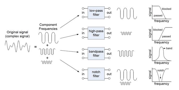
Before reading further the reader is strongly advised to review an excellent article, Introduction to Filters, from All About Circuits.  Credit to that site for the filter diagram below.

Filters can be categorized into four essential types:

  • Low-Pass: Passes frequencies below cutoff and attenuates higher frequencies
  • High-Pass: Passes frequencies above cutoff and attenuates lower frequencies
  • Band-Pass: Passes frequencies only within a specific range, attenuates others
  • Band-Stop/Band-Reject (Notch): Attenuates frequencies within a specific range, passes others

This diagram compares and clearly illustrates how these four operate:

Four filter types

Regardless of design and type, all filters will introduce some loss of the passed signal (insertion loss).  Good filter designs will minimize loss and allow the protected device to function properly.

In audio equipment the tone controls are typically high-pass and low-pass filters with adjustable cutoff for treble and bass .  More sophisticated tone controls may add a mid-range adjustment while a graphic equalizer adds filters for multiple narrow frequency ranges.

Many RFI filters are low-pass because hams may need to remove transmitted HF or VHF/UHF signals from low frequency (50/60Hz) AC power lines, audio (25Hz-25kHz) signals, VGA video (31kHz) signals, or lower-frequency (AM) radio.

Filters can be made using active circuits and/or software but more commonly, RF filtering is accomplished with simple passive electronic components: capacitors (C), inductors (L), and resistors (R).  Simple LC, RC, RL, or RLC filters can be made from combinations of these parts. The simplest low-pass filter is a capacitor across (shunt) a signal, an inductor in line (block), or both.

Besides electronic components, something completely different and maybe unexpected can also form of passive low-pass filter.  Ever wonder what that bulge is near the end of many audio, video, and computer cables?

Ferrite1

Specifically, it’s a ferrite bead or choke.  If you cut one open, under that plastic cover you would find that the cable passes through a gray tube.

220px-Ferrite_bead_no_shell

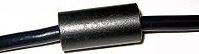
That tube is made of  ferrite material, a ceramic with high iron content and high permeability.  While more complex than this, an easy way to visualize how ferrite beads work is to say that the higher frequency signals passing through them are coupled into the material which becomes resistive over the intended frequency range and dissipates the unwanted energy as heat, while passing through the lower frequencies with minimal attenuation.

FerriteBeadAnimation

Seems a bit mysterious and magical, but it’s science.  Different ferrite compositions have varying frequency, power handling, and temperature characteristics so selection is critical.

T4A09-2018

Ferrite beads (chokes) are typically simple and inexpensive interference filters to install Continue reading

Radio Frequency Interference (RFI)

Radio frequency interference (RFI) can be a problem for hams.  We transmit radio waves which can sometimes cause problems for other electronics (radio, TV, telephones, etc.)  Sometimes other devices generate RF noise that interferes with our radio reception.

T7B03-2018

Also known as electromagnetic interference (EMI), there are several US license exam questions involving this subject.  Effects of RFI vary from nuisance audio noise or video snow to disabling electronics.

rfi1

Sometimes even normal, legal RF signals cause RFI to sensitive devices in our homes or our neighbor’s.  Even with the switch from the old analog TV broadcasts to digital format, certain ham radio transmissions can scramble over-the-air (OTA) and cable TV video and audio reception.

One common problem with cable TV interference is poor quality or improperly terminated coaxial cables.

T7B12-2018

Right or wrong, hams get blamed for any form of interference and it’s been that way for the whole century of amateur radio’s existence.  You may run across jokes and cartoons about amateur RFI like this:

interference cartoon bw

And this mock award:

WAN Award

Just be aware that hams get a lot of blame and extra scrutiny for interference, often baseless.  Still we need to be good neighbors and work with others if there is a problem.

T7B06-2018

This goes both ways.  Sometimes neighbors can cause interference with ham radio reception. Continue reading

Transmit Power

Q. How much RF power can a ham legally transmit with?

A. It varies with frequency/band, license class and licensing authority.  Maximum transmitter power levels are regulated by country; we will discuss the rules in the USA here.  It is one of the important regulatory subjects covered by the question pool for amateur radio license exams.

The average VHF/UHF handheld transceiver (HT) puts out 5 to 10W maximum.  A typical VHF mobile rig is capable of 50 to 75W.  Most modern HF transceivers peak at 100W.

Before we get to maximum levels, in the USA the general guidance is to use the least amount of power needed.

G1C04-2015

Of course, that’s easier said than done so many hams just go with the radio’s max power setting unless they know that a lower power setting works well or are operating a weak-signal mode.

In general, US hams are limited to 1500W (1.5kW) peak envelope power (PEP).  That doesn’t mean you should, just that you legally can.  This applies to General and Extra Class licensees for most bands and Technicians at VHF and higher.

T1B12-2018

There are specific power limitations on 2200m, 630m, 60m, and 30m bands:

band_chart_image_for_arrl_web

As you can see from the band plan (based on FCC regulations), Technician class licensees have 200W power limits on the HF bands, with HF privileges rather limited already.

T1B11-2018

So why a would a ham want to use more power than their stock radios can transmit, and how would they increase their default power level?

To answer the why question, it is simply that more transmit power gives more signal energy at the receiving end.  Increased wattage improves the chance of making contacts under poor conditions by overpowering signal attenuation and background noise.

To answer the how question, hams use RF amplifiers (linear power amps) to increase the power of their basic transmitter.

T7A10-2018

This RF power amplifier must operate linearly so that it does not distort the waveform.

G7B14-2015

RF amps can be for single or multiple bands.  More commonly you will find multi-band HF (or HF+6m) amplifiers which tend to be large boxes:

HF Amp

You will also find broadband or single-band VHF and/or UHF amplifiers:

Mirage 2m Amp

Besides all these commercially available amplifiers some hams build their own.  This is partly a nod to tradition—hams being DIY types—and partly because commercial amps may not be readily available for very low or high frequencies.


Ham-speak note:  When a ham says that s/he is running barefoot it means raw transmitter output power, unamplified beyond the stock radio capabilities.  Typically 100W or less.


Power amps are not just for handheld VHF/UHF FM transceivers; they can amplify most any amateur radio RF signal.  They are mainly useful for voice (AM, SSB, FM) and video Continue reading

Ham Radio Bands

The term band is thrown around constantly in ham radio discussion and it is included in  many questions in US license exam pools.  So what exactly is a radio band?

Parts of the radio frequency spectrum allocated for a common purpose are called a band.  Besides amateur radio, the reader may be familiar with USA commercial broadcast ranges known as AM band and the FM band, or another personal communication chunk of frequencies called the citizens band (CB).

With amateur radio, bands are generally associated with a number (2m or 40m, for example).  This number is approximately equal to the wavelength of that span of frequencies

t3b07-2018

We say approximately because a specific wavelength is only valid at one exact frequency and that may be outside the actual range of the band.

Shown below is a chart of the current US amateur bands (dated 2017):

band_chart_image_for_arrl_web

These 18 bands are are named by their approximate wavelength.  For those who care about such details, the named wavelength (λ) may not actually be inside the designated frequency range.  A table of these is given below:

band wavelengths

Some do, but why don’t all the meter bands line up with wavelengths inside the band?

Lots of discussion on this issue can be found on the internet and two particularly good links are given in the first two references below.  It’s a real combination of history, simplicity, misuse, and existing broadcast band names.

0.7m is the same as 700mm or 70cm; the 70cm name is more commonly used Continue reading

Indirect RF Hazards

Part 3 on Safety

Safety is an important topic in ham radio.  There are 11 questions on electrical hazards in the USA Technician class license exam pool, 13 questions on tower safety and associated grounding, and 13 questions on radio frequency (RF) hazards.

Part 1 on general electrical hazards and Part 2 on contact RF hazards were posted previously.  This post will address indirect RF hazards.  In case you are not familiar with the specifics of RF energy, refer to our post on the subject.

Here we are concerned about non-contact RF energy.  A long and involved topic (sorry about that) but full of useful detail.

While it involves radiation, RF energy radiates at lower wavelengths where it is least hazardous.

radiation spectrum.JPG

From the electromagnetic spectrum diagram above we see that radio waves are on the low end of energy levels.  As the frequency increases (wavelengths decrease) the energy in electron volts increases exponentially.  Energy above 250eV (or so) is ionizing, which in addition to radiation burns can cause cell damage and mutations, leading to cancer and other maladies, as would radioactive material.

T0C12-2018

Fortunately for hams, all radio frequencies are well below the ionizing radiation energy levels.

T0C01-2018

Ham radio operators are radio  active, not radioactive. 🙂Amateur radio activeNow just because RF radiation is non-ionizing doesn’t mean it is completely safe.  Besides the direct contact hazard, exposure to radio frequency energy may cause localized tissue heating, particularly in the eyes and male reproductive area (here’s where a lady ham has an advantage, hihi).  Non-thermal effects of RF radiation are being studied constantly because, while compelling, they are somewhat ambiguous and unproven.

Because RF energy has this radiated exposure risk, rules and regulations have arisen to protect people from such hazards.  In the USA this is done at the federal level by both the FCC (radio communications) and OSHA (occupational).  There are also guidelines for RF radiation published by the ARRL and the IEEE.  Internationally, most countries apart from the US have similar guidelines, as does the World Health Organization (WHO).  References to some of these are given at the end of this presentation.

Specific to US radio amateurs, the FCC instituted RF field exposure limits called Maximum Permissible Exposure (MPE). Continue reading

Contact RF Hazards

Part 2 on Safety

Safety is an important topic in ham radio.  There are 11 questions on electrical hazards in the USA Technician class license exam pool, 13 questions on tower safety and associated grounding, and 13 questions on radio frequency (RF) hazards.

Part 1 on general electrical hazards was posted previously.  This post will address contact RF hazards.  In case you are not familiar with the specifics of RF energy, refer to our post on the subject.  A future post will cover the broad context of non-contact or indirect RF (radiation) safety.  Both direct and indirect RF exposure will heat living tissue.

RF burn2

Here we are concerned about direct contact with a RF signal of significant energy.  This might happen if a person or animal touches a conductor carrying RF energy.  This most likely happens when someone touches an antenna element while the radio is transmitting.  It’s painful…..as in, full of pain.

T0C07-2018

Another risk of RF contact is while working on live transmitter equipment or an antenna connector.  It’s not hard to accidentally key the mic with your hands inside a transmitter enclosure or while touching an un-mated RF connector.

Human skin contact with live RF conductors is a painful experience above very low power levels. What makes it painful is that RF energy heats and damages tissue beneath the outer layer of skin, resulting in 2nd and 3rd degree burns.  Not normally superficial, RF burns heal slowly.

RF BURN

Without going into physiological details, we will simply quote one person’s testimony: “For the first half-hour or so, all I could see was a tiny dot on my fingertip, and I didn’t think much of it. As the day went on, it hurt more and more, and by the end of the day there was a big, deep, dark blister that covered my entire fingertip and hurt like hell. It took weeks to heal.”  There are some good references to RF burns at the end of this post, including a number of personal experiences.

There are a several factors involved in RF burns:  Power level (available energy), contact surface area (more is better) , grounding/return contact (less is better) and radio frequency (the body absorbs more energy at certain frequencies).

How much power is needed to create a RF burn?  Again, it varies.  There are reports of people getting fingertip burns by touching the top of the antenna connector on a relatively low-power handheld VHF transceiver (5W) and keying the PTT button with no antenna screwed in.  Obviously, a 100W HF transmitter can do much more damage than this.  You don’t need to touch a 50kW AM broadcast antenna to get a nasty RF burn.

Treatment of RF burns are just like any other type– run cold water over it and/or ice it and seek medical attention.  Avoidance is the best defense.  Of course, most RF burns are unintentional so the best we can do is make you aware.  Stay safe!

Direct RF burns cause more immediate tissue damage than indirect radiation but there is a hazard with both;  be looking for a future posting in indirect RF hazards.


RF burn references

Ham radio school

Forum with several detailed experiences reported

eHam My Very First RF Burn! interesting with experiences of many hams

EEVblog forum how does RF feel/taste? how about rf injury?

Compilation of various research studies

Biological effects of RF energy

Reddit

RF burn3.jpg

Wavelength

We recently discussed radio frequency (RF) signals and radio waves.  Now let’s review the related concept of wavelength because it is often used in ham radio.

At any frequency it takes a certain amount of time for a wave to complete one cycle.  A cycle is any repeating feature of the waveform.  Radio waves have sinusoidal form.

Wavelength cycles

Because the wave moves over time, it travels a certain distance in any given period.

Wavelength distance

Wavelength is the distance a wave travels in one complete cycle.  We measure this in meters.

T3B01-2018.png

Viewed in 3D animation, it’s not only cool to look at, but may help us understand it a little better.Wave animation
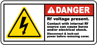
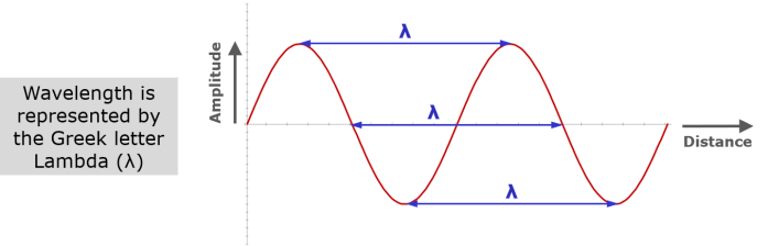
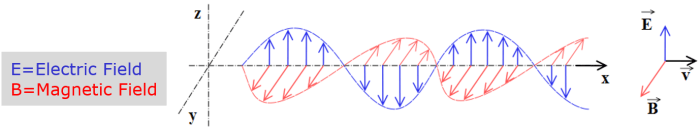
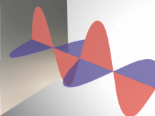
The red and blue sine waves are the electric and magnetic fields oscillating at right angles to each other at the radio frequency.  The constant wavelength (λ) follows E field peaks between the X and Z axes. The radio wave is moving along the Y axis (lower right).

Radio waves are typically oscillating millions of times per second (MHz).  They are traveling near the speed of light (300 million meters per second).

T3B11-2018.png

The time it takes for a radio wave to complete one cycle equals the speed of light (approximately) divided by the radio frequency:

300m.JPG

Simplifying the math shows us that to calculate wavelength, we simply divide 300 by the frequency in MHz.  The millions (Megas) cancel each other out.  The resultant wavelength is in meters.

T3B06-2018For the center of one popular HF band the wavelength would be:  300/14.2=21m  See how it works?

The wavelength at the center of our most common VHF radio band would be:  300/146=2.05m   

Logically, higher frequencies complete one cycle in less time than lower frequencies.

Wavelength long short.png

This means that the wavelength of higher frequencies is shorter than that of lower frequencies.  Frequency and wavelength are inversely proportional.

T3B05-2018

Wavelength is simply an inverted way of thinking about radio frequency; they are mathematically related.

It helps to visualize the two overlaid on a RF spectrum chart:

RF-spectrum-RF-Page.jpg
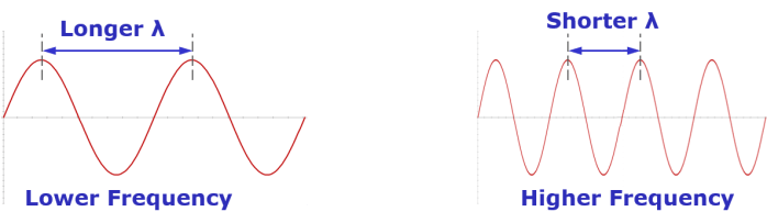
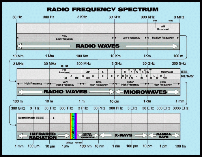
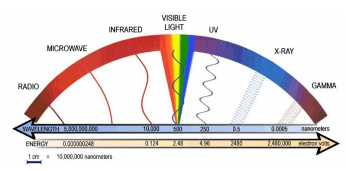
You can see how the yellow wavelength values above the blue frequencies increase in opposite directions.  Note also how the values line up in 1/10/100s and 3/30/300s per the speed of light relationship.

Wavelength becomes practical when dealing with antennas where element lengths need to be some fraction of a particular RF wavelength.

Wavelength is also the most common descriptor of radio frequency bands.  We will follow up with this in a future topic.

Wavelength is not terribly mystifying but it isn’t very obvious either.  Hopefully this gives you a better grasp of this important subject.


A fairly technical yet easily understood video relating frequency, wavelength and the speed of light is worth watching here.

Radio Frequency (RF)

Radio signals are sent via radio waves, which are a form of electromagnetic energy or radiation. T3A07-2018

Recall that a radio wave consists of both electric and magnetic fields oscillating at right angles to each other.EM Fields.png


T3B03-2018.png

Combining electrical and magnetic gives us the term electromagnetic.

T5C07-2018

Like all waves, radio waves vibrate or oscillate at a specific rate or frequency.

T5A12-2018.png

ewaves.gif
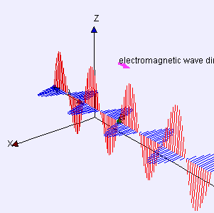
This vibration frequency is normally measured in cycles per second and its units are Hertz.  T5C05-2018.pngRates of oscillation in radio work are thousands and millions of Hertz (Hz).  With standardized metric prefixes for SI units , this means practical radio frequencies are in kHz, MHz, and GHz.

The common and familiar term RF is short for radio frequency.  It’s really an adjective, not a noun.  While we may say just RF (“You have a big RF leak, there, Fred”), we really mean radio frequency energy or signals.  RF is not a thing in and of itself.

T5C06-2018

So what is a radio frequency , then?  They are a large chunk of frequencies in the middle of the electromagnetic spectrum (the range of possible frequencies from 0 to measurably high).  Technically radio frequencies start at low audio frequencies and run up to just below infrared light, basically 30Hz-300GHz.  Different sources specify other upper/lower boundaries because a more practical range is the low frequency band up through microwaves.  However you define it, this range of frequencies is  known as the radio spectrum.

RF Spectrum.gif

While hams can use very low frequencies on one end and go up to microwave frequencies at the high end, the more common radio amateur frequencies are in the shortwave, VHF, and UHF range.

We will follow up with detailed posts on the important topics of RF wavelength and amateur radio bands, along with RF safety.  Coming soon to Newhams.info; stay tuned.


Flat Ground Strap

Ever wonder why RF grounds should be flat straps and not regular wires?

This is because ordinary wires are not good conductors at frequencies higher than 50-60Hz. This complicates wiring and bonding requirements.

Impedance (effectively, AC resistance) of a conductor increases with frequency and length due to inductive reactance.  The higher the frequency, the greater the impedance.

XL

All conductors have some measurable inductance, and it doesn’t take much to yield significant impedance.  At KHz or MHz frequencies, long round wires might present hundreds or even thousands of Ohms impedance; not suitable for grounding.

A good ground has less than one ohm impedance.  This is a genuine safety issue.

G4C05-2015

Since inductive reactance increases with frequency and length, safety grounds and module bonds need to be something other than long round wires when radio frequencies are involved.

When high frequency grounding is required, use short, wide, and flat conductive straps.  The high aspect ratio minimizes electrical inductance vs. a round wire, as does a short conductor.  This lowers the ground wire’s impedance at higher frequencies.

T4A08-2018

So now you know.  Keep it flat and short (KIFS is a lousy acronym).

It’s not just a suggestion; this one might just bite you if you don’t heed the guideline!

RF Connector Types

The plug that is used for terminating cables between the receiver, transmitter or transceiver and the antenna is generally referred to as the RF connector because it carries the Radio Frequency signal to/from the equipment.

In addition to mating the radio to the antenna via a transmission line (usually a coaxial cable) it may also used on RF test equipment (antenna analyzer, power and SWR meters, spectrum analyzer) and dummy loads.  All hams should be familiar with different RF connectors so we’ll give a brief high-level description here.

Good news!  There are only four common types of RF connector used in ham radio:


PL-259

220px-uhf_pl_connector     250px-uhf-connector

By far the most common RF connector, the PL-259 is used to connect most all modern HF transceivers and VHF/UHF mobile rigs to the antenna.  The PL designation stands for plug and the 259 is an old US Signal Corps assignment.  It has a male center pin and female thread.

t9b07

The mating  receptacle found on the radios and equipment is known as a SO-239.  SO for socket, it features a female center receptacle and has male threads.

so-239

The PL-259 and SO-239 combination (details here) is frequently referred to as a “UHF connector” although this designation comes from the 1930s when UHF was considered anything above 30MHz.  It has performance limitations above 100MHz so other connector types are more suitable for true UHF use.

g6b13


N-type Continue reading