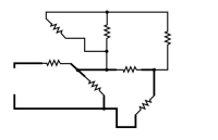
All hams should have at least a limited understanding of basic circuits, and this means being able to differentiate between series and parallel components.
Besides numerous license exam questions (dozens below in green boxes; knowing helps you pass the exams), some technical discussions in ham radio will throw the terms around so let’s explore the matter here. In addition to our own presentation, some excellent web references are given at the end for further (and often more interesting) information.

Before jumping into circuits, let’s discuss series and parallel connections. Visualizing this will help us understand series and parallel circuits.
As the name suggests, series connections are lined up end-to-end.

We’re demonstrating with resistors but the principle applies to any two-terminal component: capacitors, inductors, diodes, cells/batteries, and light bulbs can all be wired in series with two or more of each (or a mix of different parts). Lining them up terminal to terminal makes a series connection.

Schematically, 3 parts in series looks like this:
![]()
From this simple schematic we intuitively see that the current flowing through a series string has to be the same though the chain; there is nowhere else for electrons to flow (current).

Equal current is one way of defining a series circuit.

Also as the term suggests, parallel connections are side-by-side.

Again, demonstrating with resistors and again, the principle applies to any two terminal component. Arranging components across each other makes a parallel connection.

Schematically, 3 parts in parallel looks like this:

From this simple schematic we intuitively see that the voltage across parallel components must be the same.

Equal voltage is one way of defining a parallel circuit.

We just learned that current is the same through components in series, and voltage is the same across components in parallel. What about the voltage across series components, and current through parallel components?
![]()
Based on the electrical properties of series components, the voltage across each will be proportional to their impedance (following Ohm’s Law), since the same current flows through both parts.

The sum of each will always equal the end-to-end voltage in a series string. If both parts have the same value, the voltage will divide equally.

Based on the electrical properties of the parallel components, the current through each will be inversely proportional to their impedance (following Ohm’s Law), since the same voltage appears across both parts.

The sum of each will always equal the end-to-end current in a parallel string. If both parts have the same value, the current will divide equally.
Applying the concept of series and parallel connections to circuits, first we must understand exactly what is a circuit. An electric circuit is at its most basic a path for current to flow from one pole of a DC or AC voltage source to the other.
The simplest circuit consists of a light bulb controlled by an on/off switch.

As you can imagine, most circuits are more complicated than this, although they can often be broken down into simpler individual ones for easier analysis and understanding.
When the three basic passive component types are combined in series or parallel, we get some interesting results. Resistors and inductors in series simply add their values together (Rtotal=R1+R2+Rn; Ltotal=L1+L2+Ln).


Capacitors in parallel add their values together (Ctotal=C1+C2+Cn).


Conversely, capacitors in series divide their capacitance according to the formula . With equal values it works out simply to divide the unit value by the number of components.

Resistors and inductors in parallel divide their values per the formulae and .
When resistors are unequal the net value will always be less than the smallest resistor.

With equal values it works out simply to divide the unit value by the number of components.


Batteries in series add their voltage together; identical batteries in parallel have the same voltage with multiplied current capacity (Ah).
Except for the most rudimentary of circuits, most real electronics circuits are formed by a combination of series and parallel components. Don’t worry, you don’t have to know or understand this, just be aware.
If this doesn’t make complete sense or if you want to dive more deeply into the topic, there are many web links below to help explain better, with good graphics and some videos.
Sorry for the long but foundational entry. We bring up the series/parallel topic because some future posts will involve the concept. Be on the lookout for those and hopefully this will better prepare you to understand.
Interesting/Useful Web Links
What are “Series” and “Parallel” Circuits? – All About Circuits
Series and parallel circuits – Wikipedia Topic
Series and Parallel Circuits – SparkFun (includes video)
What is the Difference Between Series and Parallel Circuits? – Autodesk
Series vs Parallel Circuits – YouTube video
Two Simple Circuits: Series and Parallel – YouTube video
What’s a Circuit, Series and Parallel – ElectroBOOM video (Explosive Humor)

 . With equal values it works out simply to divide the unit value by the number of components.
 and
and  .
.