The standing wave ratio (SWR) is an important topic to hams regardless if they are working HF, VHF, UHF or any other frequency range allocated to radio amateurs. Unfortunately it is technically involved and somewhat complex so is not intuitive or easy for non-technical folks to understand. We’ll give a simplified explanation of SWR here and give you a basic idea of its significance and how hams relate to it.
The simplest way to think of SWR is as a measure of impedance matching. Most commonly it is looking at the impedance differences between transceiver, transmission line (more often coaxial cable), and antenna.

Assuming that all modern radios and cable have 50Ω impedance, the real SWR of interest boils down to the match between the transmission line and antenna.
As we mentioned in a previous post, when impedance of a source equals load impedance the best possible signal coupling occurs. Conversely, when impedances are not the same, signals couple poorly. This is true of all electronics circuitry involving AC waveforms.
In amateur radio SWR focus is on transceiver to antenna coupling where we want to maximize RF power transfer in both transmit and receive modes. When impedances do not match, received signals will be weak or non-existent; when transmitting, power will not radiate well from the antenna. The ideal or “perfect” SWR for best possible transmit/receive coupling is 1:1, meaning a 50Ω radio/transmission line to a 50Ω antenna.

SWR is simply the ratio of two impedances being measured. It is commonly expressed in the X:X format and the larger value is always given first, regardless of which side is higher.

With a 50Ω radio and 50Ω coax cable, a 4:1 SWR could indicate either a 12.5Ω or a 200Ω load (antenna). Similar examples for 50Ω cable are contained in the General class exam pool:

 A ham’s main concern with high SWR is significant power reflected back from the load, which stresses the transmitter power amplifier. While a 1:1 SWR is ideal, practically speaking, 1.5:1 or less is good. Many modern transceivers automatically reduce transmit power with a SWR greater than 2:1.

SWR can be measured using an in-line SWR meter. The meter is installed between the transceiver and antenna, usually somewhere in the feed/transmission line (typically close to the radio for easy viewing at the operator position).

An alternative to a SWR meter is a directional RF power or Watt meter (or wattmeter).

Installed in the same location, a directional power meter can be used by subtracting the reflected power from the forward power to determine how good the impedance match is. Some are cleverly scaled with SWR indication where the two needles cross (cross-needle wattmeter).
Additionally, antenna analyzers are popular modern devices which measure SWR of the transmission cable and antenna without the transceiver connected. They are a great way to check your antenna system impedance independently.

Whether using a SWR meter or directional Watt meter, the frequency response of the meters must be appropriate for the bands of operation. HF meters will not read properly on VHF or UHF bands, and vice-versa.
Another useful benefit of a SWR meter is to help identify intermittent or loose connections in an antenna or connecting cable. These can cause wild swings in SWR as the impedance changes when a cable is flexed, wind blows, or moisture corrodes connections.

Impedance matching of radios to feed line and/or antenna is typically accomplished with matching networks (balun, unun) and antenna “tuners”.

Tuners being more common, they are variable impedance matching circuits with adjustable inductors and/or capacitors that change the resonance of a particular load at a certain frequency. Tuners may be external or internal to a transceiver.

This is sort of a trick question in the General class pool. They are giving us a 5:1 load (antenna and feed line) and a 1:1 match. The 1:1 match does not change the 5:1 load; it would have to be a 5:1 match to compensate for the load.
One last thought about SWR and antennas. A low SWR is desirable but that by itself doesn’t mean that the antenna will work well. Resonance, height and efficiency are also major factors in antenna performance, among other things. A 50Ω dummy load will have a perfect 1:1 SWR but still be a poor radiator.
Boring, yes. A dry topic, but very important to amateur radio. For those who are really interested there are plenty of technical details to be found on the internet and a basic explanation of SWR is given below.
When there is a mismatch between the load impedance and the transmission line, part of the forward wave sent toward the load is reflected back along the transmission line towards the source. The source then sees a different impedance than it expects which can lead to lesser (or in some cases, more) power being supplied by it, the result being very sensitive to the electrical length of the transmission line.
Such a mismatch is usually undesired and results in standing waves along the transmission line which magnifies transmission line losses (significant at higher frequencies and for longer cables). The SWR is a measure of the depth of those standing waves and is, therefore, a measure of the matching of the load to the transmission line. A matched load would result in an SWR of 1:1 implying no reflected wave. An infinite SWR represents complete reflection by a load unable to absorb electrical power, with all the incident power reflected back towards the source.
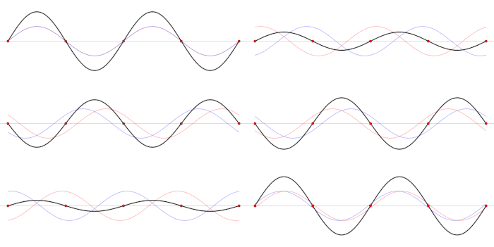
 Incident wave (blue) is fully reflected (red wave) out of phase at short-circuited end of transmission line, creating a net voltage (black) standing wave. Γ = −1, SWR = ∞
The term standing wave is derived from the observational characteristic of nodes in the resulting waveform being motionless (standing), the red dots in the animated graphic above.
The standing wave ratio (SWR) is the difference between the maximum and minimum waveform values along the transmission line and is directly a function of the difference between impedance from input to output of a system.
To help visualize impedance and standing waves, there is an outstanding video from the AT&T archives called Similarities of Wave Behavior.
The video presentation is old (1961) but there is nothing else quite like it. It is expertly presented, very interesting, and quite applicable to understanding radio waves in antennas and feedlines.
Highly recommended for all hams to spend a half hour watching this video.

SWR. I’ve been around radio all my life and I’m still not sure I fully understand SWR!!!
LikeLike
Hi Richard, hope you watch the old AT&T video linked in the post. It should really help your understanding of SWR. 73 and cheers from across the pond! Jim
LikeLike
Great AT&T video. Very clever model!
LikeLike
Great article, and I appreciate the link to the video!
Regarding G9A08-2015, I interpret the discussion above to imply that the tuning is “wrong” (i.e. the tuner is set to a value it should have if there was no mismatch at the load) and therefore isn’t compensating for the 5:1 load impedance. I am not certain that is the situation described by the problem.
My understanding of this question is that it is intended to communicate the fact that even when the tuner is matched correctly and presents a 1:1 load to the transmitter that does not change the fact that the 5:1 mismatch is still present at the antenna end of the feedline and high SWR still exists on the line which can result in increased signal loss if the line itself is lossy. The tuner does not eliminate the mismatch; it simply hides the mismatch from the transmitter and protects the transmitter amplifier.
73 de AE4ON
LikeLike
Daniel, I have always thought this General class exam question was awkward.
One way to look at it is, if you have a 5:1 mis-match and you add a 1:1 impedance transformer (or tuner), the 5:1 SWR is passed through. Practically speaking, you solve no problem. Personally, I don’t see a lot of value with this question, except perhaps to get people to think about impedance matching in general. It’s almost a trick question. I haven’t looked at the next exam question set and would not be surprised to find this question gone or re-phrased. Jim
LikeLike